1. Produkt Overview
The Dioche 24V 350W Brushless Motor Controller is designed to provide stable speed and sensitive control for braking and direction changes in electric bicycles and scooters. Its aluminum alloy shell offers excellent heat dissipation, protecting the internal circuitry from thermal overloading. The durable wires and interfaces are designed for long-term reliability and feature clear labels for straightforward installation.
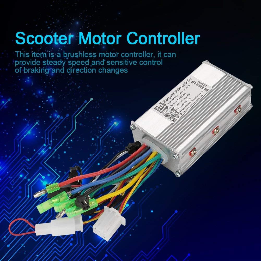
Image 1.1: The Dioche 24V 350W Brushless Motor Controller, showcasing its compact design and array of connection wires.
2. Spesifikaasjes
| Eigenskip | Spesifikaasje |
|---|---|
| Rated Working Voltage | 24V |
| Rated Power | 350W |
| Aktueel | 13A |
| Low Voltage beskerming | 21V |
| Suitable Motor Phrase Angle | 60 / 120 graad |
| Materiaal | Aluminium alloy |
| Ofmjittings (L x B x H) | Ongeveer 9 x 5.3 x 3 sm (3.5 x 2 x 1.18 inch) |
| Gewicht | Approx. 200g (0.2 Kilograms) |
3. Safety Information
- Skeakelje altyd de stroom út foar ynstallaasje, ûnderhâld of probleemoplossing.
- Soargje derfoar dat alle ferbiningen feilich en goed isolearre binne om koartslutingen te foarkommen.
- Do not expose the controller to water or extreme temperatures.
- Ferifiearje dat de voltage and power ratings of your motor and battery are compatible with this controller.
- Sykje profesjonele help as jo net wis binne oer ynstallaasjestappen.
4. Opset en ynstallaasje
Carefully follow these steps to install your brushless motor controller. Refer to the labels on the controller's interfaces and the provided diagrams for correct connections. Incorrect wiring can damage the controller or other components.

Image 4.1: Detailed wiring diagram for the Dioche Brushless Motor Controller, showing labeled connectors for various functions.
Ferbiningsstappen:
- Motor Cables (A, B, C): Connect the three thick motor phase wires (typically green, yellow, blue) from the controller to the corresponding motor phase wires. Ensure colors match.
- Hall Sensor: Connect the Hall sensor wire bundle (usually a 5-wire connector) from the controller to the motor's Hall sensor connector.
- Batterij ferbining:
- Battery Positive Electrode: Connect the red wire from the controller to the positive terminal of your 24V battery.
- Battery Negative Electrode: Connect the black wire from the controller to the negative terminal of your 24V battery.
- Speed Steering Handle (Throttle): Connect the throttle connector (typically a 3-wire connector) to the speed control handle.
- Low Potential Brake: Connect the brake signal wire(s) to your brake levers. This connection typically cuts power to the motor when brakes are applied.
- Assist Sensor (PAS): If your electric bicycle has a pedal-assist system, connect the assist sensor wire to the corresponding connector.
- Intelligent Identification (Self-Learning Wires): These two wires (often white or green) are used for initial motor direction setup. Connect them, power on, and the motor will spin. If it spins in the wrong direction, disconnect, reconnect, and power on again. Once the correct direction is established, disconnect and leave them disconnected.
- Cruisefunksje: If your system supports a cruise control function, connect the cruise function wires.
After all connections are made, double-check each wire against the labels and diagrams before applying power.

Ofbylding 4.2: Close-up view of various connectors and the controller's identification label, aiding in correct wiring.
5. Bedriuwsinstruksjes
- Ensure all connections are secure and the battery is charged.
- Turn on the main power switch of your electric vehicle.
- Use the speed steering handle (throttle) to control the motor's speed.
- Apply brakes as needed; the controller will cut power to the motor when the brake signal is received.
- If equipped, engage the cruise function for maintaining a constant speed.
6. Underhâld
- Hâld de controller skjin en frij fan stof en pún.
- Regularly inspect all wire connections for looseness or damage.
- Avoid exposing the controller to direct sunlight for prolonged periods or to environments with high humidity.
- Besykje de controller net te iepenjen casing, as this may void any warranty and could lead to damage.
7. Probleemoplossing
- Motor reagearret net: Check battery charge, ensure all power connections are secure, and verify throttle connection. Re-check the intelligent identification wires if motor direction was an issue.
- Intermitterende macht: Inspect all wiring for loose connections or damaged insulation. Ensure the battery is providing consistent voltage.
- Overheating Controller: Ensure the controller is mounted in a location with adequate airflow. Verify that the motor is not drawing excessive current due to a fault or overload.
- Remmen snije gjin krêft ôf: Check the low potential brake wire connection and ensure the brake levers are functioning correctly.
8. Garânsje en stipe
This product is covered by a standard manufacturer's warranty against defects in materials and workmanship. For specific warranty terms and duration, please refer to the documentation provided at the time of purchase or contact your retailer.
For technical support or inquiries, please contact the seller or manufacturer directly. Provide your product model number and purchase details for efficient assistance.